How Do Spacecraft Dock in Orbit?

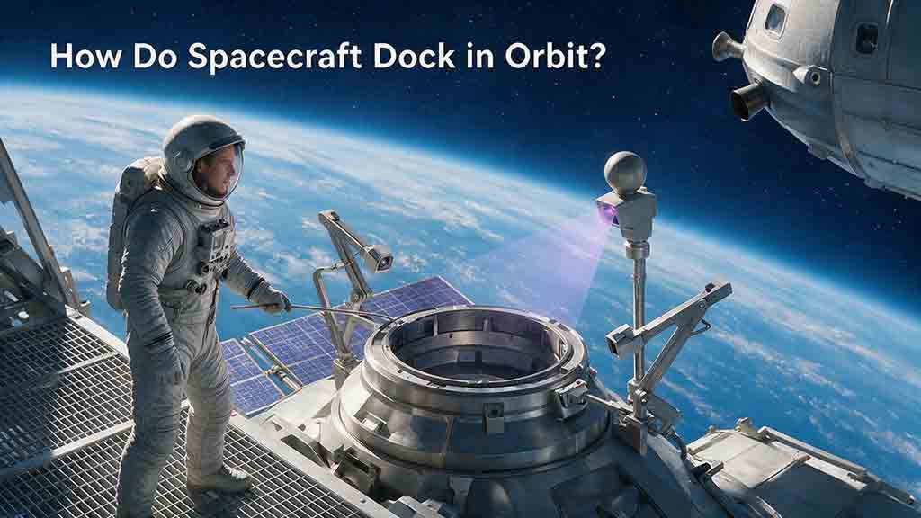
How Do Spacecraft Dock in Orbit?
Spacecraft dock in orbit by gradually matching their trajectories, timing, relative position, velocity, and orientation. The approaching spacecraft then follows a controlled corridor toward the target, makes a low-energy initial connection called soft capture, and completes hard capture with structural hooks or latches. For pressurized crew or cargo transfers, teams verify pressure integrity before opening the hatches.
Key Takeaways
- Orbital docking begins with rendezvous, not a direct flight toward the target.
- The spacecraft must match relative position, velocity, timing, attitude, and interface geometry.
- Cameras, radar, lidar, radio links, inertial sensors, and navigation software may work together during the approach.
- Soft capture absorbs residual motion before hard capture creates a rigid structural connection.
- A credible docking plan includes hold, retreat, abort, or collision-avoidance options.
This guide explains the process from orbital phasing to physical connection. It also shows why a lower orbit can help a spacecraft catch its target, how docking differs from berthing, what can interrupt an approach, and how engineers balance time, propellant, accuracy, mechanical tolerance, and safety.
What Are the Main Stages of Spacecraft Docking?
NASA commonly groups the activities involved in orbital docking under rendezvous, proximity operations, and docking, abbreviated as RPOD. These activities combine trajectory design, navigation, propulsion, attitude control, flight software, communications, mechanical systems, testing, and mission operations.
NASA describes this multidisciplinary work in its overview of rendezvous, proximity operations, and docking subsystems.
A docking mission can be understood as five connected stages:
| Stage | Primary objective | Typical systems involved | Safe response if limits are exceeded |
|---|---|---|---|
| Rendezvous | Reach the target’s orbital neighborhood | Propulsion, orbit determination, ground tracking | Retarget or remain in a safe orbit |
| Proximity operations | Control relative motion near the target | Radar, lidar, cameras, radio links, flight software | Hold, retreat, or abort |
| Final approach | Align with the docking axis | Relative-navigation sensors and attitude control | Stop or back away |
| Soft capture | Make initial contact and absorb residual motion | Capture ring, guides, dampers, capture latches | Stabilize or separate |
| Hard capture and verification | Create a rigid connection and check required interfaces | Structural hooks, seals, sensors, electrical connections | Keep transfers or hatches inhibited |
Conceptual docking sequence — not to scale:
Phasing orbit → Far-field rendezvous → Hold point → Final approach → Soft capture → Hard capture → Interface verification
A hold or retreat may occur at more than one point. The sequence is a conceptual map, not a vehicle-specific flight procedure.
Which Conditions Must Match Before Docking?
Two spacecraft are ready to dock only after several different types of mismatch have been reduced to acceptable limits.
A useful way to organize the problem is the five-match framework.
| Required match | Operational question | Why it matters |
|---|---|---|
| Orbital geometry | Do the spacecraft have compatible trajectories for the planned rendezvous? | The vehicles need a controlled way to enter the same operational region. |
| Orbital phase | Will both spacecraft reach the meeting region at the correct time? | Similar orbits do not guarantee physical proximity. |
| Relative state | Are relative position and velocity known and controlled? | Excessive closing or sideways motion can make the approach unsafe. |
| Attitude | Are the docking ports pointed and rotated correctly? | Matching position alone does not align the interfaces. |
| Interface compatibility | Can the ports capture, carry loads, and support the required services? | Similar-looking ports are not necessarily compatible. |
For many low-Earth-orbit missions, compatible orbital geometry means closely matching the target’s orbital plane. Lunar, cislunar, and other complex environments may use relative trajectories that are not well described as two nearly coplanar circular orbits.
Why is matching altitude not enough?
Two spacecraft can orbit at the same altitude while remaining thousands of kilometers apart. They can also pass through the same region at different times or travel with incompatible relative velocities.
Docking therefore requires control of a six-dimensional relative state:
- Three components of relative position
- Three components of relative velocity
The spacecraft must also control orientation and angular motion. In practical terms, the ports must reach the same place at the same time, with nearly the same velocity and the correct rotational alignment.
Why Can’t a Spacecraft Fly Straight Toward Its Target?
A spacecraft in orbit is continuously falling around a planet or moon. A thruster firing changes the spacecraft’s orbit, so it changes where the vehicle will be several minutes or several revolutions later.
Pointing directly at the target and accelerating is therefore not equivalent to driving toward a stationary object. The maneuver could raise or lower the chaser’s orbit, alter its orbital period, create an unsafe crossing path, or produce excessive relative velocity at arrival.
Rendezvous guidance predicts how each burn will change the future motion between the two spacecraft.
Why can a lower orbit help a spacecraft catch up?
For an approximately circular Earth orbit, the orbital period is:
[T = 2\pi\sqrt{\frac{a^3}{\mu}}]
where:
- (T) is the orbital period,
- (a) is the orbit’s semi-major axis,
- (\mu) is Earth’s gravitational parameter.
A lower circular orbit has a smaller semi-major axis and a shorter period. A spacecraft in that orbit completes each revolution sooner and gradually gains angular position on a spacecraft in a slightly higher orbit.
This produces a result that initially seems counterintuitive:
- A spacecraft behind its target may temporarily enter a lower phasing orbit to catch up.
- A spacecraft too far ahead may use a higher phasing orbit so the target can gain on it.
The exact maneuver depends on the initial geometry, propulsion system, navigation uncertainty, thermal limits, debris environment, and destination rules.
1. Launch is timed for compatible orbital geometry
A visiting spacecraft normally launches during a window that allows it to enter an orbit compatible with the target.
For a station in low Earth orbit, Earth’s rotation must bring the launch site into a useful alignment with the station’s orbital plane. Launching near the required plane is important because a large inclination change after reaching orbit can consume substantial propellant.
The launch vehicle does not usually place the spacecraft directly beside the target. It inserts the chaser into an initial orbit from which later maneuvers can control timing and separation.
2. The chaser enters a phasing orbit
The chaser is the spacecraft performing the approach. The target is the spacecraft or station being approached.
The chaser uses one or more maneuvers to create an orbital period slightly different from the target’s. By remaining in this phasing orbit for a planned time, the chaser changes its angular position relative to the target.
Mission planners balance:
- Rendezvous duration
- Propellant consumption
- Communications coverage
- Lighting conditions
- Crew workload
- Thermal limits
- Navigation opportunities
- Space-debris avoidance
- Destination traffic
- Docking-port availability
A rapid rendezvous reduces transit time but leaves less time for system evaluation. A longer profile provides more opportunities for navigation updates and troubleshooting but increases operational workload.
3. Transfer burns reduce the orbital separation
Once the phase relationship is suitable, the chaser performs targeted burns that raise, lower, or reshape its orbit.
The purpose is not merely to reach the target’s altitude. The chaser must arrive at a planned relative position, with a safe relative velocity and an approach geometry that preserves separation if a later maneuver is missed.
Correction burns may compensate for:
- Navigation uncertainty
- Maneuver-execution errors
- Atmospheric drag
- Timing errors
- Spacecraft mass-property uncertainty
- Orbital perturbations
During this stage, the spacecraft may still be tens or hundreds of kilometers apart.
4. Navigation transitions from absolute to relative measurements
At long range, each spacecraft can be navigated mainly with respect to Earth or another central body. As the chaser approaches, navigation increasingly focuses on the target.
Relative navigation estimates the chaser’s position, velocity, orientation, and sometimes angular rate with respect to the target spacecraft.
NASA’s spacecraft navigation overview explains how orbit determination, reference trajectories, and correction maneuvers support controlled spaceflight.
Relative navigation may combine:
- Satellite-navigation measurements in supported regions
- Ground-based orbit estimates
- Inter-spacecraft radio measurements
- Radar range and range rate
- Lidar measurements
- Optical camera images
- Reflectors or visual docking targets
- Inertial measurement units
- Star trackers
- Thruster and attitude telemetry
Different sensors have different strengths. A camera can provide accurate bearing and orientation information while offering weaker range information from a single image. Radar or lidar can measure range precisely but may face field-of-view, visibility, or reflection limitations.
Combining several measurement types helps the flight computer detect inconsistent data.
5. The chaser begins proximity operations
Proximity operations begin when the spacecraft are close enough that an incorrect maneuver could threaten either vehicle.
The chaser may pass through several predefined approach points rather than flying continuously toward the port. At a hold point, onboard software, crews, and mission controllers can confirm that the conditions for continuing have been met.
Checks may include:
- Relative position and velocity
- Agreement between navigation sensors
- Propulsion-system readiness
- Attitude-control performance
- Communications quality
- Target-spacecraft orientation
- Docking-port configuration
- Approach-corridor clearance
- Remaining retreat and abort capability
Hold-point locations are specific to each vehicle and mission.
6. The spacecraft enters an approved approach corridor
The final approach usually follows a defined corridor aligned with the docking port.
The corridor creates predictable geometry for:
- Navigation sensors
- Docking targets
- Lighting
- Communications
- Thruster-plume constraints
- Structural clearance
- Collision-avoidance planning
During Automated Transfer Vehicle operations, the European Space Agency used an approach architecture in which the vehicle flew automatically while crew members monitored video imagery to confirm that it remained inside the permitted corridor. ESA describes this arrangement in its overview of rendezvous and docking operations.
The chaser must control both translation and rotation. Its docking port must face the target port, maintain the required roll orientation, and avoid excessive angular motion.
7. Final approach reduces relative motion
During final approach, the flight computer repeatedly:
- Measures the relative state.
- Estimates navigation uncertainty.
- Predicts the future trajectory.
- Compares the prediction with the permitted corridor.
- Commands small corrections.
- Confirms that the correction had the expected effect.
Important controlled quantities include:
- Range
- Closing rate
- Lateral position error
- Lateral velocity
- Angular alignment
- Angular rate
- Sensor confidence
- Available propellant
- Time and clearance for retreat
Both spacecraft may be traveling around Earth at several kilometers per second. Docking is possible because their velocities are closely matched. Near contact, the critical quantity is their velocity relative to each other, not their speed relative to Earth.
8. Soft capture creates the initial connection
Soft capture is the first mechanical attachment between the docking systems.
The soft-capture mechanism is designed to tolerate small remaining errors in position, angle, velocity, and angular motion. Guide features align the interfaces, capture latches prevent immediate separation, and compliant or damped components reduce residual movement.
Revision G of the International Docking System Standard, developed through the international IDSS partnership and dated January 23, 2026, describes soft-capture functions that align, capture, arrest, and stabilize the vehicles before hard capture.
Soft capture is not yet the final structural connection. The spacecraft may still move slightly relative to each other while the mechanism dissipates energy and improves alignment.
9. Hard capture creates a rigid structural connection
After the remaining motion has been reduced and the docking rings are aligned, the mechanism draws the structural interfaces together.
Hooks or latches close around the interface. This hard-capture stage creates the rigid connection needed to transfer structural loads and position seals or service connections correctly.
During the Crew Dragon Demo-2 mission in 2020, NASA reported soft capture followed by the closure of 12 hooks to complete hard capture. Leak checks and pressurization followed before the hatches were opened. NASA documented the sequence in Crew Dragon Docks to Space Station.
Depending on the mission, hard capture may establish connections for:
- Electrical power
- Data communications
- Electrical grounding and bonding
- Ventilation
- Thermal-control services
- Fluid transfer
- Crew or cargo passage
Unpressurized docking missions may proceed directly to structural, electrical, data, or fluid-interface checks rather than leak checking or hatch opening.
10. For pressurized docking, seal integrity is verified before hatch opening
A rigid mechanical connection does not automatically prove that the passage between two pressurized spacecraft is airtight.
The volume between the closed hatches is normally isolated and monitored. Mission teams may:
- Confirm hard-capture indications
- Check the connecting volume for leakage
- Equalize pressure
- Configure ventilation
- Verify electrical connections
- Confirm valve and seal status
The hatches remain closed until the required checks have been completed successfully.
What Sensors Help Spacecraft Dock?
No single sensor is ideal at every distance. Docking systems therefore use different measurements as the chaser moves from far-field rendezvous to final contact.
| Sensor or data source | Information provided | Most useful stage | Important limitation |
|---|---|---|---|
| Satellite-navigation receiver | Absolute position and velocity | Phasing and far-field rendezvous | Availability and geometry vary by location |
| Ground tracking | Independent orbit estimates | Long-range rendezvous | Depends on communications coverage and processing |
| Inter-spacecraft radio | Range, range rate, bearing, or data exchange | Far and medium range | Requires compatible equipment and link geometry |
| Radar | Range, range rate, and sometimes direction | Medium and close range | Reflections and field of view can affect measurements |
| Lidar | Precise range and direction | Close approach | Surface properties and target visibility matter |
| Optical camera | Bearing, target recognition, and alignment | Close approach and final docking | One image may provide limited range information |
| Visual docking target | Known pattern for estimating orientation | Final approach | Must remain visible and illuminated |
| Star tracker | Spacecraft attitude relative to stars | Throughout the mission | Bright objects or obstruction can interfere |
| Inertial measurement unit | Short-term acceleration and rotation | Maneuvers and attitude control | Errors accumulate without external updates |
| Contact and force sensors | Contact and interface-load information | Capture | Useful only near physical contact |
A low-Earth-orbit spacecraft may rely heavily on satellite navigation. A lunar rendezvous vehicle may depend more on optical, radio, and inertial measurements because Earth-based navigation signals are less useful or unavailable.
Who Controls the Docking?
Modern docking operations normally divide responsibility among onboard computers, crew members, destination operators, mission control, and independent safety logic.
| Participant | Typical responsibilities |
|---|---|
| Onboard flight computers | Process sensor data, estimate relative state, command guidance and control, and monitor limits |
| Crew in the approaching spacecraft | Monitor performance, confirm readiness, command holds or aborts, and use manual control if available |
| Crew or operators at the target | Configure the docking port, monitor the corridor, and respond to anomalies |
| Mission control | Assess trajectory and system status, coordinate both vehicles, and support major decisions |
| Independent safety logic | Detect selected hazardous conditions and initiate a predefined response |
NASA’s description of Crew Dragon’s first demonstration mission explains how the vehicle demonstrated autonomous approach, retreat, and docking functions while mission teams monitored the operation.
Automation does not eliminate human involvement. Computers process navigation measurements continuously and can respond rapidly within programmed limits. Human operators contribute judgment, cross-system coordination, and responses to unexpected conditions.
Manual control is not automatically safer than autonomous control. Safety depends on navigation quality, software verification, displays, training, fault detection, communications, and available escape trajectories.
What Is the Difference Between Docking and Berthing?
Docking and berthing both attach a visiting vehicle to another spacecraft or station, but the final capture process differs.
| Feature | Docking | Berthing |
|---|---|---|
| Final movement | The visiting spacecraft flies into the interface | The spacecraft stops at a capture position |
| Initial capture | The docking mechanism captures directly | A robotic arm or external system grapples the vehicle |
| Final positioning | The docking system completes capture | The robotic system moves the vehicle to the interface |
| Visiting-vehicle requirement | Precise final-approach and docking capability | Less responsibility for final physical placement |
| Destination requirement | Compatible docking port | Robotic capture and berthing infrastructure |
| Common application | Crew and autonomously docking cargo vehicles | Some cargo vehicles and station modules |
Crew Dragon was designed to approach and dock with the International Space Station using its own navigation, propulsion, software, and docking mechanism.
NASA explains that earlier cargo Dragon spacecraft were captured with the station’s robotic arm rather than completing direct autonomous docking.
Cygnus spacecraft have also been captured with Canadarm2 and attached through a berthing interface. NASA provides an example in Cygnus Berthed to Space Station.
Neither method is universally superior.
Docking reduces dependence on robotic capture infrastructure and may support faster crew access or departure. Berthing allows an external robotic system to control final placement. Some station berthing interfaces have large transfer openings, but hatch size depends on the specific interface rather than on berthing itself.
How Does a Docking Mechanism Handle Contact?
Even a highly accurate guidance system leaves small residual errors at contact. The docking mechanism must manage position error, angular error, closing motion, and rotation without damaging either spacecraft.
The mechanism performs three main jobs.
Capture
Latches or equivalent features establish the initial connection before the vehicles can drift apart.
Attenuation and alignment
Compliant structures, dampers, actuators, guide petals, or similar features reduce motion and guide the interfaces into position.
A simplified representation of the translational kinetic energy involved is:
[E_{\text{relative}} =\frac{1}{2}m_{\text{effective}}v_{\text{relative}}^2]
For an idealized one-dimensional interaction between two freely moving bodies, the effective mass is their reduced mass:
[m_{\text{effective}} =\frac{m_1m_2}{m_1+m_2}]
Real docking analyses also account for vehicle flexibility, rotational motion, control-system behavior, off-center contact, damping, structural modes, and capture-mechanism dynamics.
Because kinetic energy increases with the square of relative velocity, doubling the contact velocity would produce four times the translational energy under the same simplified assumptions. This is one reason closing rates are kept low.
Structural mating
Hard-capture hooks or latches pull the structural rings together and maintain the required preload. Seals, guide pins, electrical contacts, and other interface features can then reach their designed positions.
A large soft-capture envelope can tolerate greater guidance error, but it may require more mechanism travel, structural strength, actuator capability, mass, and testing.
A smaller capture envelope can simplify the hardware but demands more accurate navigation and control. Docking design therefore trades spacecraft precision against mechanical tolerance.
How Much Difference Can a Small Phasing-Orbit Change Make?
Consider a simplified example involving two spacecraft in circular, coplanar Earth orbits.
Assumptions
- Target altitude: 400 kilometers
- Chaser phasing altitude: 390 kilometers
- Reference Earth radius: approximately 6,378 kilometers, close to Earth’s equatorial radius
- Earth gravitational parameter: approximately (398{,}600\ \text{km}^3/\text{s}^2)
- Atmospheric drag, Earth’s nonspherical gravity, finite-duration burns, navigation errors, and mission safety constraints are ignored
Using:
[T = 2\pi\sqrt{\frac{a^3}{\mu}}]
the approximate orbital periods are:
| Spacecraft | Orbital radius | Approximate period |
|---|---|---|
| Target at 400 km | 6,778 km | 5,554 seconds, or 92.56 minutes |
| Chaser at 390 km | 6,768 km | 5,541 seconds, or 92.36 minutes |
The chaser completes an orbit about 12.3 seconds sooner.
The approximate angular gain during one target orbit is:
[\Delta\theta =360^\circ\left(\frac{T_{\text{target}}}{T_{\text{chaser}}}-1\right)]
[\Delta\theta \approx 0.80^\circ]
If the chaser begins 10 degrees behind the target, the idealized number of orbits needed to remove the phase difference is:
[N \approx\frac{10^\circ}{0.80^\circ}\approx 12.5\ \text{orbits}]
The corresponding time is:
[t \approx12.5 \times 92.56\ \text{minutes}\approx 19.3\ \text{hours}]
The 19.3-hour estimate begins after the chaser is assumed to be established in the 390-kilometer circular phasing orbit. The maneuvers used to enter and leave that orbit would also affect the real phase history and total rendezvous time.
This calculation is not an operational rendezvous plan. A real mission would also require maneuver targeting, navigation updates, correction burns, uncertainty analysis, safe approach geometry, and authorization to begin proximity operations.
NASA JPL publishes reference astrodynamic parameters used in mission analysis and higher-fidelity calculations.
How Do Docking Approaches Stay Safe?
A safe approach is designed so that one bad measurement, missed maneuver, or failed command does not automatically produce a collision.
A practical way to understand the safety architecture is the detect, hold, separate, and verify framework.
Detect abnormal behavior
The spacecraft may monitor:
- Closing rate
- Lateral position
- Attitude error
- Angular rate
- Sensor agreement
- Thruster response
- Computer status
- Communications health
- Remaining propellant
- Docking-system readiness
Independent sensors or software paths can reduce the chance that one faulty measurement remains undetected.
Hold before uncertainty becomes hazardous
A hold stops the planned progression while keeping the spacecraft in a controlled relative condition.
Mission teams can use the pause to compare measurements, evaluate hardware, update navigation, or wait for the target spacecraft to become ready.
Separate when continuing is unsafe
A retreat moves the chaser away from the docking port so the problem can be assessed before another attempt.
An abort or collision-avoidance maneuver creates a more decisive separation when the vehicle cannot safely continue or remain at the current hold point.
The safe direction is not always simply backward. Orbital motion must be considered so that the chaser does not drift back toward the target later.
Verify every major transition
The operation proceeds only after telemetry confirms that the previous event occurred correctly.
Examples include confirming that:
- A maneuver produced the expected trajectory
- Navigation sensors agree
- The docking port is configured
- Soft capture is established
- Relative motion has been stabilized
- Hard-capture hooks are closed
- Required interfaces pass their checks
What happens when the system detects a problem?
| Detected condition | Why it matters | Typical high-level response |
|---|---|---|
| Navigation sensors disagree | The relative state may be uncertain | Hold, compare data, reacquire the target, or retreat |
| Closing rate is too high | Contact loads and collision risk increase | Stop the approach or separate |
| Vehicle leaves the corridor | The path to the port may no longer be safe | Correct within limits or retreat |
| Attitude error is excessive | The interfaces may contact at an unsafe angle | Pause, back away, and realign |
| Docking port is not ready | Capture may be impossible or unsafe | Remain at a hold point |
| Control-system fault occurs | Precise relative-motion control may be lost | Enter a safe mode or abort |
| Communications are lost | Mission teams may be unable to verify the approach | Follow the programmed loss-of-communication response |
| Soft capture is not confirmed | Hard capture may begin without a stable connection | Stop the mating sequence |
| Hard-capture indication is incomplete | Structural integrity may be uncertain | Keep transfers and hatches inhibited |
| Pressurized seal check fails | The passage may not be airtight | Isolate the volume and keep hatches closed |
These are general design responses, not vehicle-specific crew instructions.
“The spacecraft catches up by accelerating toward the target”
A velocity change alters the chaser’s orbit. Depending on the burn direction, accelerating may increase the orbital period instead of producing a direct closing motion.
“The vehicles are together once they reach the same altitude”
Altitude is only one condition. Timing, orbital geometry, relative velocity, attitude, and port alignment must also be controlled.
“Docking is one impact”
Docking is a controlled sequence: contact, soft capture, motion attenuation, alignment, hard capture, and interface verification.
“Autonomous docking needs no human supervision”
Autonomous software may execute the guidance and control, but mission teams normally monitor critical operations and retain defined intervention options.
“Any standardized-looking port can connect”
Port diameter and appearance do not prove compatibility. Engineers must verify capture geometry, loads, seals, clearances, electrical interfaces, software behavior, environmental limits, and certification.
The International Docking System Standard supports interoperability by defining common interface requirements. It does not replace vehicle-specific analysis and testing.
What Tradeoffs Shape a Docking Mission?
| Design choice | Main advantage | Main tradeoff |
|---|---|---|
| Faster rendezvous | Reduces transit time | Leaves less time for checks and corrections |
| Slower rendezvous | Provides more evaluation opportunities | Increases mission duration and workload |
| Greater autonomy | Reduces reliance on continuous ground commands | Requires extensively verified software |
| Greater human control | Adds judgment and adaptability | Depends on training, workload, displays, and communications |
| Large capture envelope | Tolerates larger contact errors | Adds mass and mechanical complexity |
| Small capture envelope | Can simplify the mechanism | Requires more precise navigation |
| Direct docking | Avoids robotic capture infrastructure | Requires a capable visiting vehicle and compatible port |
| Robotic berthing | Lets an external system control final placement | Depends on destination robotics |
| Standardized interface | Supports potential interoperability | Does not guarantee mission compatibility |
There is no single best rendezvous profile. The preferred design depends on the destination, propulsion system, communications architecture, crew status, target cooperation, acceptable risk, and required departure capability.
How Do Low-Earth-Orbit and Lunar Docking Differ?
The objective is similar in every environment: reduce relative position, velocity, and orientation errors until controlled contact is possible.
The trajectory and navigation architecture can differ substantially.
Low Earth orbit
A spacecraft approaching a station in low Earth orbit may benefit from:
- Satellite-navigation signals
- Frequent ground communications
- Established tracking networks
- Short communication delays
- Repeated phasing opportunities
- Mature station approach procedures
Low Earth orbit also introduces atmospheric drag, debris hazards, traffic coordination, and clearance constraints around large structures and solar arrays.
Lunar and cislunar space
A lunar or cislunar rendezvous may involve:
- Limited access to Earth-based navigation signals
- Longer communication delays
- Greater onboard autonomy
- Different lighting conditions
- More complex orbital geometries
- Greater reliance on optical and radio navigation
- Different hold, retreat, and escape trajectories
A rendezvous near a near-rectilinear halo orbit cannot be treated as a copy of an International Space Station approach. The local dynamics, navigation methods, safe regions, and abort options require a different design.
How Can You Evaluate a Docking Plan?
The following checklist helps determine whether a mission description explains a complete docking architecture or only shows the final contact.
Orbital approach
- Which spacecraft is the chaser?
- Which spacecraft maintains the target attitude?
- How is compatible orbital geometry established?
- How is the phase difference reduced?
- Where does navigation change from absolute to relative measurements?
Guidance and sensors
- Which sensors measure range?
- Which sensors measure bearing and orientation?
- Are independent measurements compared?
- Can the approach remain safe after losing one sensor?
- Is the final approach autonomous, manual, or supervised autonomous?
Safety architecture
- Where are the hold points?
- Which conditions must be satisfied before continuing?
- What causes a retreat?
- What causes an abort or collision-avoidance maneuver?
- Can the chaser separate without drifting back toward the target?
- What happens after loss of communications?
Mechanical interface
- Which docking or berthing interface is used?
- What errors can soft capture tolerate?
- How is contact energy absorbed?
- How is hard capture confirmed?
- Which structural, electrical, data, pressure, or fluid services cross the interface?
Post-contact operations
- Which mechanical and service connections are checked?
- Is the connection pressurized or unpressurized?
- How is pressure integrity verified when applicable?
- When can electrical, data, ventilation, or fluid services be activated?
- Can either spacecraft depart rapidly if required?
What This Article Does Not Claim
This article explains general rendezvous and docking principles. It is not a flight procedure, crew checklist, engineering specification, or substitute for vehicle-specific mission documentation.
The phasing calculation uses a simplified circular-orbit model. It does not include atmospheric drag, finite-duration burns, navigation covariance, launch dispersions, plume impingement, structural constraints, traffic coordination, or destination-specific safety rules.
A spacecraft should not be assumed compatible with a docking port merely because both reference the same general standard. Compatibility requires detailed interface analysis, testing, certification, software verification, and operational agreement.
Practical Conclusion
Orbital docking is fundamentally a process of removing relative differences in a controlled order. The chaser establishes compatible orbital geometry and timing, measures and reduces relative motion, enters a protected approach corridor, and makes low-energy contact.
The most useful mental model is:
Match the orbit → measure relative motion → approach in stages → absorb contact → lock and verify.
Students can explore the process by calculating how small altitude changes affect orbital period and phase. Readers comparing real missions should examine the navigation sensors, hold points, escape options, capture mechanism, and post-contact checks. Professional planning must rely on current vehicle requirements, interface-control documents, and approved operational procedures.
Sources
NASA Johnson Space Center — Rendezvous, Proximity Operations, and Docking Subsystems
Overview of NASA RPOD engineering, guidance, navigation, control, testing, simulation, and mission-design work.NASA Science — Basics of Space Flight, Chapter 13: Navigation
Background on orbit determination, reference trajectories, navigation, and trajectory correction.European Space Agency — Rendezvous and Docking
Explanation of Automated Transfer Vehicle rendezvous, onboard sensors, approach-corridor monitoring, automation, and crew oversight.International Docking System Standard Interface Definition Document, Revision G
International interface requirements covering docking geometry, soft capture, hard capture, and interoperability.NASA — Crew Dragon Docks to Space Station
Operational example documenting soft capture, closure of 12 hard-capture hooks, leak checks, and pressurization.NASA — Crew Dragon Ready for First Launch
Description of Crew Dragon’s autonomous approach, retreat, navigation, propulsion, and docking demonstrations.NASA — Cygnus Berthed to Space Station
Example of a cargo spacecraft being captured with Canadarm2 and attached through a berthing interface.NASA Jet Propulsion Laboratory — Astrodynamic Parameters
Reference astrodynamic constants and parameters used in mission analysis.
Editorial Approach
This guide is based on published NASA, NASA JPL, European Space Agency, and International Docking System Standard materials rather than private mission data or claimed hands-on spacecraft testing.
The five-match framework, detect-hold-separate-verify safety model, conceptual sequence map, and docking-plan evaluation checklist are editorial tools created to organize established rendezvous and docking principles for general readers. They are not official mission procedures.
The orbital-period example was calculated independently using the standard circular-orbit equation and rounded public parameters. It is presented as an educational estimate rather than a high-fidelity trajectory analysis.
Historical examples are included to illustrate established processes such as autonomous approach, corridor monitoring, soft capture, hard capture, pressure verification, and robotic berthing.
More from Mission Operations & Exploration
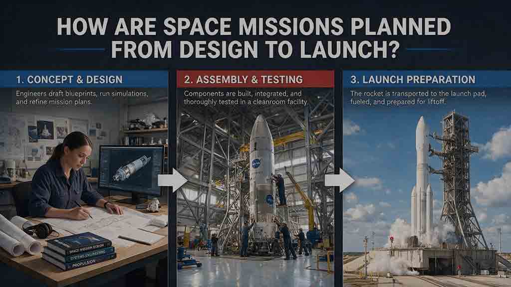
How Are Space Missions Planned From Design to Launch?
Space missions are planned by transforming a scientific, commercial, or exploration goal into a complete system that can be designed, built, tested, launched, operated, and responsibly concluded. This guide follows the full planning lifecycle, from defining measurable objectives and comparing mission concepts to writing requirements, selecting an architecture, managing resource budgets, and controlling interfaces. It explains how payloads, spacecraft platforms, trajectories, launch services, software, ground systems, regulations, and operations must be developed together. Readers will also learn how design reviews, fabrication, environmental testing, end-to-end verification, operator training, licensing, launch integration, and readiness assessments support mission development. Original planning frameworks, worked mass, power, and data calculations, troubleshooting guidance, and a practical checklist show how teams identify weak assumptions and resolve designs that do not close. The central lesson is that mission readiness depends on the entire technical and operational system—not merely on completing the spacecraft.
What Happens During a Rocket Launch Countdown?
A rocket launch countdown is far more than a clock running toward zero. It is a carefully coordinated process that brings the launch vehicle, spacecraft, ground equipment, flight teams, weather conditions, and safety range into an approved configuration for liftoff. This article explains the major countdown phases, including launch-pad preparation, propellant loading, avionics and navigation checks, weather monitoring, range clearance, go/no-go polls, and terminal count. It also clarifies commonly misunderstood terms such as T-minus, L-minus, planned hold, recycle, scrub, and launch window. An original Four-C Countdown Framework—Clock, Configuration, Constraint, and Commitment—helps readers understand why teams may continue, pause, return to an earlier step, or cancel a launch attempt. Practical timelines, comparison tables, a launch-window calculation, and a viewer’s checklist make the article useful for students, educators, first-time launch viewers, and spaceflight enthusiasts.
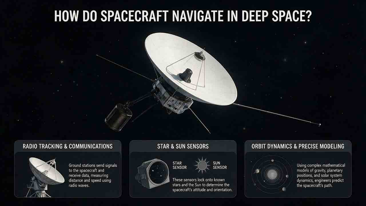
How Do Spacecraft Navigate in Deep Space?
Spacecraft navigate in deep space by comparing a predicted trajectory with repeated radio, optical, and onboard measurements. Ground networks measure distance, line-of-sight velocity, and angular direction. Cameras add destination-relative observations, while attitude sensors establish the spacecraft’s pointing direction. Navigation software combines those observations with force models, estimates position and velocity with uncertainty, and determines whether a trajectory correction is needed.
Explore More Topics
How Do Spacecraft Return Safely Through Earth’s Atmosphere?
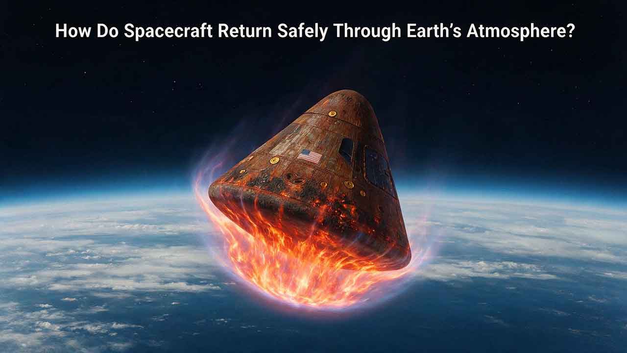
Spacecraft return safely through Earth’s atmosphere by managing an enormous amount of energy through a carefully coordinated sequence of trajectory control, thermal protection, aerodynamic deceleration, landing, and recovery. This article explains how deorbit burns and entry corridors guide a spacecraft toward its landing region, why blunt heat shields reduce the danger of hypersonic heating, and how guidance systems control attitude, range, and structural loads. It includes an original comparison of low-Earth-orbit and lunar-return energy, a practical review of ablative and reusable heat-shield technologies, and the CosmoBasics Four-Layer Reentry Framework covering path, protection, control, descent, and recovery. Real-world lessons from Artemis I and the crewed Artemis II mission show why postflight inspection remains essential even after a successful splashdown. Readers will also learn how parachutes, wings, landing rockets, flotation systems, and recovery teams complete the return safely.
How Do Astronauts Sleep, Eat, and Exercise in Space?
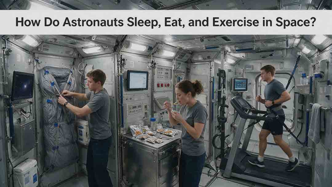
Astronauts must redesign ordinary routines when they live in microgravity. This article explains how crew members sleep in secured bags inside ventilated quarters, prepare packaged meals without letting food or liquids drift through the cabin, and use specialized exercise equipment to protect their physical condition. It examines the roles of the Advanced Resistive Exercise Device, the T2 treadmill, and the CEVIS cycle ergometer, while clarifying the difference between active workout time and the full scheduled exercise period. Readers will also learn why tortillas are practical in space, how airflow affects sleep, why ordinary weights do not work normally in orbit, and how nutrition, rest, and exercise support one another. NASA and ESA sources provide the factual foundation, while original comparison tables and practical evaluation frameworks show how spacecraft systems replace functions normally supplied by gravity. The article also distinguishes current International Space Station practices from possible future Moon and Mars mission requirements.
What Happens to the Human Body in Microgravity?
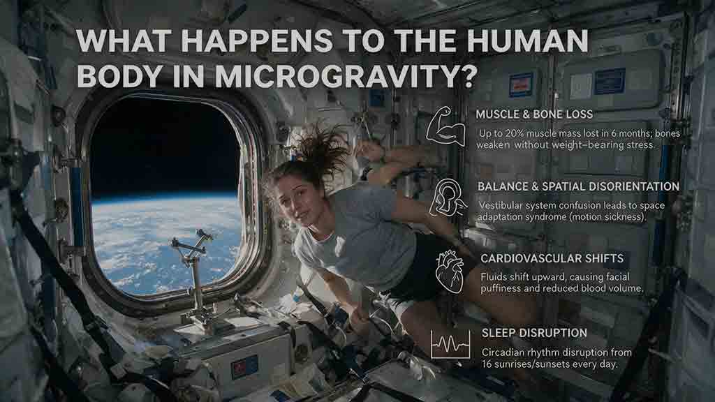
Microgravity changes the human body because fluids are no longer pulled toward the legs, muscles and bones receive less mechanical loading, and the brain loses gravity as a dependable orientation signal. This article explains how weightlessness affects balance, circulation, muscle strength, bone density, vision, blood, immunity, digestion, sleep, and spinal length. It also examines why astronauts may struggle to stand or walk after landing and how exercise, nutrition, monitoring, and rehabilitation help reduce these risks. Two original tools—the Load–Flow–Orientation Framework and the Gravity-Transition Readiness Matrix—connect physiological changes with real mission demands. Drawing on NASA standards, NASA technical reports, ESA materials, and peer-reviewed human spaceflight research, the guide clearly separates established observations from experimental countermeasures and unresolved questions. It also explains what these effects could mean for future missions to the Moon and Mars without treating population averages as predictions for individual astronauts.