How Do Spacecraft Generate Electricity?

How Do Spacecraft Generate Electricity?
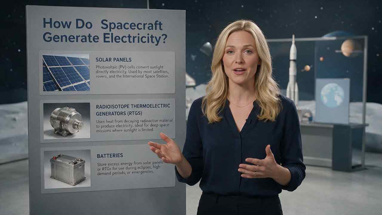
Spacecraft generate electricity mainly by converting sunlight with photovoltaic solar arrays. Missions that cannot depend on sunlight may use radioisotope power systems, fuel cells, primary batteries, or, in rare cases, fission reactors. Rechargeable batteries usually store previously generated energy, while power-management electronics regulate and distribute electricity to computers, instruments, radios, heaters, and propulsion equipment.
Key Takeaways
- Solar arrays are the most common long-duration power source when a spacecraft has adequate access to sunlight.
- Rechargeable batteries bridge eclipses, deployment periods, temporary power peaks, and emergency operating modes.
- Radioisotope power systems generate electricity from heat released by natural radioactive decay and do not require sunlight.
- Fuel cells and primary batteries are useful when mission duration and stored reactants or energy can be defined in advance.
- A spacecraft needs a complete power architecture—not merely a generator with the highest wattage rating.
This guide follows electricity from its original energy source to the equipment that uses it. It also explains how engineers compare power options, estimate solar-array and battery requirements, recognize common power limitations, and avoid misleading technology comparisons.
The Complete Spacecraft Power Flow
A spacecraft electrical power system must perform several connected jobs:
Energy source → Power conversion → Voltage regulation → Energy storage → Power distribution → Spacecraft loads → Waste-heat rejection
Possible energy sources include sunlight, radioactive decay, stored chemical reactants, battery chemistry, and nuclear fission. The resulting electricity is conditioned before being delivered to spacecraft equipment.
Rechargeable batteries may be connected to the regulated power bus so that excess generation can be stored and later returned to the system.
Simplified educational architecture: This flow map was developed for this article. It is not to scale and does not represent the wiring or redundancy architecture of a particular spacecraft.
How Do Spacecraft Generate Electricity Step by Step?
The electricity used by a spacecraft normally passes through seven functional stages.
1. The Mission Provides an Energy Source
Every electrical system begins with an available form of energy.
Depending on the mission, that energy may come from:
- Sunlight striking photovoltaic cells
- Heat released by radioactive decay
- Chemical reactants supplied to a fuel cell
- Chemical energy stored in a primary battery
- Heat produced by a controlled fission reaction
The destination, mission duration, lighting conditions, power demand, mass limit, and acceptable system complexity determine which sources are practical.
2. The Energy Is Converted Into Electricity
Solar cells convert part of the energy in sunlight into direct-current electricity through the photovoltaic effect.
A radioisotope thermoelectric generator converts a temperature difference into electricity through thermoelectric materials. A fuel cell generates electricity through an electrochemical reaction. A fission system produces heat first and then requires a separate conversion system to produce electricity.
A primary battery also converts chemical energy directly into electrical energy, but it carries a finite supply that is not normally replenished.
3. The Electrical Output Is Conditioned
The voltage and current leaving a source may vary with temperature, illumination, battery condition, and operating state. They may also differ from what individual instruments require.
Power-conditioning equipment can include:
- Voltage regulators
- DC-to-DC converters
- Battery charge controllers
- Current limiters
- Switching devices
- Fault-protection circuits
- Solar-array power trackers
- Local converters for individual loads
There is no universal spacecraft bus voltage. Engineers select an architecture based on total power, component compatibility, cable losses, conversion efficiency, fault tolerance, and mission heritage.
4. Surplus Energy Is Stored
When generation exceeds immediate demand, a rechargeable battery can store part of the surplus.
Stored energy may later support the spacecraft during:
- A planetary eclipse
- Launch and early operations
- Solar-array deployment
- Off-Sun pointing
- A communications transmission
- A high-power scientific observation
- An emergency or safe mode
NASA reports that solar power is the predominant source for small spacecraft. Its 2026 Small Spacecraft technology review states that more than 90% of the nanosatellite and SmallSat form factors covered by the review use solar panels with rechargeable batteries.
Source: NASA Small Spacecraft Systems Virtual Institute — Power
5. Power Is Distributed to Spacecraft Loads
The power-management and distribution system routes electricity to the equipment that needs it.
Typical spacecraft loads include:
- Flight computers
- Attitude-control electronics
- Sensors and scientific instruments
- Radios and antenna systems
- Pumps and valves
- Thermal-control heaters
- Cameras and radar equipment
- Deployment mechanisms
- Electric-propulsion power processors
Critical loads normally receive greater protection and higher priority than optional science or convenience loads.
6. Loads Are Scheduled and Protected
A spacecraft rarely operates every device at maximum power simultaneously.
Onboard software and mission planners may schedule instruments, communications, heating, and propulsion at different times. This reduces peak demand and gives the battery time to recharge.
If available power falls too low, the spacecraft may:
- Turn off nonessential instruments
- Reduce heater duty cycles
- Postpone a transmission
- Shorten an observation
- Stop electric propulsion
- Enter a low-power safe mode
Protection circuits can also isolate an electrical fault so that one failed load does not disable the entire system.
7. Waste Heat Is Rejected
No electrical conversion process is perfectly efficient. Solar cells, converters, batteries, transmitters, computers, and nuclear power systems all produce heat.
A spacecraft cannot cool its electronics through ordinary air convection. Heat must be conducted through the structure or thermal hardware and ultimately emitted from radiators as infrared radiation.
Power design and thermal design are therefore inseparable. A system that produces enough electricity but cannot reject its waste heat may still be unusable.
Which Power Sources Do Spacecraft Use?
The principal options are solar arrays, radioisotope power systems, batteries, fuel cells, and fission power systems.
| Power source | Original energy | Typical application | Main advantages | Important limitations |
|---|---|---|---|---|
| Solar photovoltaic array | Sunlight | Earth-orbiting satellites and many planetary missions | Renewable during the mission, scalable, mature | Depends on illumination, orientation, distance, temperature, deployment, and degradation |
| Radioisotope power system | Natural radioactive decay heat | Long-duration missions with weak, unreliable, or unavailable sunlight | Continuous output, useful heat, no solar pointing required | Limited electrical output, gradual decline, specialized safety and approval requirements |
| Fuel cell | Stored chemical reactants | Defined-duration missions carrying suitable reactants | Generates electricity continuously while reactants remain; may also produce useful water | Reactants are consumed, limiting total mission energy |
| Primary battery | Stored chemical energy | Short probes, launch phases, return capsules, and backups | Simple, compact, immediately available | Normally cannot be recharged; stored energy is finite |
| Rechargeable battery | Previously generated electricity | Eclipse support, peak loads, safe mode, and load leveling | Rapid response and repeated use | Stores rather than creates net mission energy; performance declines with age and cycling |
| Fission system | Controlled nuclear fission heat | Potential high-power surface or deep-space systems | High continuous power independent of sunlight | Complex conversion, shielding, deployment, safety, and heat-rejection requirements |
No power source is automatically best. The correct comparison is between complete mission architectures, including storage, regulation, thermal control, redundancy, deployment, and end-of-life performance.
How Do Solar Panels Generate Electricity in Space?
Solar cells generate electricity when incoming photons transfer energy to charge carriers in semiconductor materials. The resulting movement of charge produces direct current.
Individual cells are connected into strings. Strings are assembled into panels, and one or more panels form a solar array. Large arrays may unfold after launch and rotate to maintain a favorable orientation toward the Sun.
What Is the Difference Between a Solar Cell, Panel, and Array?
These terms describe different levels of the same system:
- A solar cell is an individual photovoltaic device.
- A solar panel is a structural assembly containing multiple connected cells.
- A solar array is the complete electricity-generating assembly, which may include several panels, hinges, wiring, drives, and deployment equipment.
Using the terms interchangeably can hide important differences between cell efficiency and the output of a complete flight array.
Why Are Space Solar Cells Different From Rooftop Panels?
Space-qualified solar cells must continue operating through conditions that terrestrial panels do not normally experience, including:
- Launch vibration and acoustic loads
- Vacuum
- Repeated hot and cold cycles
- Ultraviolet exposure
- Charged-particle radiation
- Micrometeoroid impacts
- Long-term material degradation
- Strict mass and area limits
Many spacecraft use multi-junction solar cells. These cells contain multiple semiconductor layers that capture different portions of the solar spectrum.
The European Space Agency describes efficiencies around 30% for advanced space solar cells. That figure describes the cells under specified conditions, not the net efficiency of an installed spacecraft array.
Source: ESA — Power Systems
Array-level output is lower after accounting for:
- Cell temperature
- Wiring losses
- Conversion losses
- Pointing error
- Cell mismatch
- Structural gaps
- Radiation damage
- Shielding or cover glass
- Partial shadowing
- Failed cells or strings
How Does Distance From the Sun Affect Solar Power?
Available sunlight decreases approximately with the square of the distance from the Sun.
A simplified relationship is:
S(r) = S₀ / r²
Where:
- S(r) is solar irradiance at the destination
- S₀ is solar irradiance near one astronomical unit
- r is the distance from the Sun in astronomical units
NASA gives a representative total solar irradiance near Earth’s orbital distance of approximately 1,361 watts per square meter. The value varies slightly over time and with orbital distance.
Source: NASA Goddard — Solar Irradiance Science
This inverse-square relationship means that a spacecraft at five astronomical units receives approximately:
1 / 5² = 1 / 25
of the sunlight available near Earth, before other losses are considered.
Distance does not create an exact boundary beyond which solar power becomes impossible. It progressively increases the required array area, efficiency, deployment complexity, and operational discipline.
Can Solar Power Work Near Jupiter?
Yes, for missions designed around the limitations.
NASA’s Juno became the first solar-powered spacecraft to operate at Jupiter. NASA notes that Jupiter receives about 4% of the sunlight available near Earth.
Source: NASA Science — Juno
Europa Clipper also uses solar power. Its arrays are large enough that the fully deployed spacecraft spans more than 100 feet, or about 30 meters.
Source: NASA Science — Meet Europa Clipper
These missions demonstrate technical feasibility, not universal superiority. A Jupiter orbiter, atmospheric probe, surface system, or high-power spacecraft may face different radiation, darkness, geometry, and load requirements.
Why Do Solar-Powered Spacecraft Need Batteries?
Solar arrays cannot support every operating condition directly.
Batteries may be needed because:
- Earth or another body blocks the Sun
- The arrays are stowed after launch
- The spacecraft must point an instrument away from the Sun
- A transmitter or radar creates a temporary power peak
- The array is partially shadowed
- An emergency requires immediate backup power
- Available sunlight has declined below nominal expectations
The Hubble Space Telescope provides a clear example. Hubble’s two solar arrays generate electricity and charge six batteries while the observatory is illuminated. The batteries support Hubble when Earth blocks its view of the Sun.
Source: NASA Science — Hubble Electrical Power
Do Batteries Generate Electricity or Only Store It?
A battery converts chemical energy into electrical energy. Its mission role depends on whether it is a primary or rechargeable battery.
Primary Batteries
A primary battery is installed with a finite supply of stored chemical energy and is not normally recharged.
Primary batteries are well suited to applications such as:
- Short atmospheric probes
- Launch vehicles
- Sample-return capsules
- Short entry, descent, and landing phases
- Emergency or independent backup systems
NASA notes that primary spacecraft batteries commonly support single-use operations lasting from minutes to hours and, in some cases, days.
Source: NASA Science — Energy Storage Technologies for Future Planetary Science Missions
Rechargeable Batteries
A rechargeable battery, also called a secondary battery, stores electricity generated elsewhere.
It may be recharged by:
- Solar arrays
- A radioisotope power system
- A fuel cell
- A fission power system
- Ground equipment before launch
Rechargeable batteries are commonly used for eclipses, load leveling, short power peaks, and safe-mode support.
Why Watts and Watt-Hours Are Different
Power and energy answer different questions.
- Watts measure power: the rate at which electricity is generated or consumed.
- Watt-hours measure energy: the total electrical work available over time.
For example, a 500-watt instrument operating for two hours requires:
500 W × 2 h = 1,000 Wh
A battery may store enough watt-hours for the operation but still be unable to deliver the required peak current. A different battery may support a large peak but run out of energy quickly.
Spacecraft power budgets must therefore consider both instantaneous power and total energy.
How Do Radioisotope Power Systems Generate Electricity?
A radioisotope power system uses heat released by the natural decay of a radioactive isotope.
The systems used for several NASA planetary missions rely on plutonium-238 heat sources supplied through a NASA–U.S. Department of Energy partnership.
Source: U.S. Department of Energy — What Is a Radioisotope Power System?
A radioisotope thermoelectric generator, or RTG, converts part of this heat into electricity using thermoelectric materials. Traditional RTGs perform this conversion without turbines or other continuously moving machinery.
Is an RTG a Nuclear Reactor?
No.
An RTG uses heat from natural radioactive decay. It does not create or control a sustained fission chain reaction.
A fission reactor operates through controlled splitting of atomic nuclei. It is a different technology with different materials, control requirements, power levels, thermal behavior, and safety considerations.
Why Use a Radioisotope Power System?
Radioisotope power can be useful when a mission faces:
- Weak sunlight
- Long periods of darkness
- Dust that may cover solar panels
- Extreme cold
- Difficult solar pointing
- Long mission duration
- A requirement for continuous low-level power
The unused heat can also help keep components within their operating-temperature range.
NASA’s Curiosity and Perseverance Mars rovers use Multi-Mission Radioisotope Thermoelectric Generators. The systems provide electrical power and usable heat without requiring daily solar charging.
Sources:
What Are the Limitations of Radioisotope Power?
A radioisotope system does not provide unlimited or constant lifetime output.
Its electrical output declines gradually because of:
- Radioactive decay
- Long-term changes in conversion materials
- Increasing spacecraft power demand relative to available output
- Battery aging in systems that use a battery for peak loads
Radioisotope systems also require specialized fuel production, containment, testing, safety analysis, launch approval, and mission justification.
They are valuable for missions that need their particular capabilities, but they are not a universal replacement for solar arrays.
How Do Fuel Cells Generate Electricity in Space?
A fuel cell converts the chemical energy of supplied reactants directly into electricity through an electrochemical reaction.
Unlike a rechargeable battery, a conventional fuel cell can continue generating electricity as long as reactants are supplied. Its total mission energy is therefore limited by the stored reactants and supporting hardware.
NASA used hydrogen–oxygen fuel cells during Apollo missions and aboard the Space Shuttle. The reaction produced electricity, heat, and water.
Source: NASA — Moon Missions and Fuel Cell Development
Fuel cells were suitable for those vehicles because mission duration, crew needs, reactant storage, and the wider vehicle architecture were planned together.
That does not mean fuel cells are inherently better than solar arrays. A long-duration uncrewed satellite with reliable sunlight may gain little from carrying consumable reactants.
Can Spacecraft Use Fission Reactors?
Yes, although fission electrical systems have been rare in U.S. spaceflight.
A fission reactor produces heat through a controlled chain reaction. That heat must then be converted into electricity by a thermoelectric, dynamic, or other conversion system.
The spacecraft must also reject unused heat through radiators.
SNAP-10A, launched in 1965, remains the only fission power reactor launched into space by the United States.
Source: NASA — Utilization of Space Nuclear Systems
NASA and the U.S. Department of Energy continue to study fission power for future lunar-surface and other high-power applications.
Source: NASA — Fission Surface Power
Potential advantages include high continuous output and independence from local sunlight. Challenges include mass, conversion equipment, launch and deployment requirements, shielding decisions, thermal rejection, safety analysis, and program approval.
This article addresses those systems only at a high educational level. It does not provide reactor construction, fuel-processing, handling, or operational instructions.
How Is Spacecraft Electricity Regulated and Distributed?
The subsystem that controls and routes electricity is commonly described as power management and distribution, or PMAD.
PMAD functions may include:
- Regulating solar-array output
- Controlling battery charging
- Converting bus voltage
- Switching individual loads
- Measuring voltage and current
- Isolating electrical faults
- Limiting excessive current
- Prioritizing essential equipment
- Reporting telemetry to the flight computer
- Protecting batteries from unacceptable operating conditions
The exact architecture varies. Some spacecraft use a tightly regulated bus. Others allow the main bus voltage to change within a defined range and regulate power closer to individual loads.
NASA identifies power generation, storage, and distribution as central parts of a spacecraft electrical power system.
Source: NASA Small Spacecraft Systems Virtual Institute — Power
What Is a Spacecraft Power Budget?
A power budget is an accounting model showing how much electrical power and energy each subsystem needs in each mission condition.
A useful budget distinguishes at least:
- Average operating load
- Maximum simultaneous load
- Eclipse or no-generation load
- Emergency safe-mode load
- Battery-recharge demand
- End-of-life generation capability
Engineers also include allowances for:
- Wiring loss
- Converter loss
- Battery aging
- Solar-cell degradation
- Temperature
- Pointing error
- Manufacturing variation
- Uncertain operating conditions
- Failed cells, strings, or components
- Future changes in mission scheduling
Designing only for average consumption is risky. A spacecraft may generate enough energy over a full day and still experience a damaging voltage drop when several high-power loads start together.
Worked Example: Estimating Solar-Array Output
The following example is an independent educational calculation. It is not based on a specific spacecraft and must not be used as a flight design.
Assumptions and Their Status
| Input | Value | Status |
|---|---|---|
| Solar irradiance near 1 AU | 1,361 W/m² | NASA reference value |
| Illuminated solar-cell area | 6 m² | Assumed for the example |
| Cell efficiency | 30% | Assumed representative value |
| End-of-life performance factor | 0.77 | Assumed teaching value |
| Pointing and conditioning factor | 0.85 | Assumed combined teaching value |
| Normal spacecraft load | 900 W | Assumed mission demand |
| Battery-recharge allocation | 300 W | Assumed mission demand |
| Design margin | 20% | Assumed margin |
The array area represents illuminated cell area, not necessarily the outer dimensions of the deployed structure.
Step 1: Estimate Array Output
Use the simplified relationship:
Power = Irradiance × Area × Cell efficiency × End-of-life factor × System factor
Substituting the assumed values:
Power = 1,361 × 6 × 0.30 × 0.77 × 0.85
Estimated power ≈ 1,603 W
The estimated output under the stated assumptions is approximately 1.6 kilowatts.
Step 2: Estimate Required Generation
The spacecraft must support its normal load and recharge allocation:
900 W + 300 W = 1,200 W
Applying the assumed 20% margin:
Required generation = 1,200 × 1.20
Required generation = 1,440 W
The estimated array output exceeds the calculated requirement by approximately:
1,603 W − 1,440 W = 163 W
That reserve is relatively small. A real engineering analysis would test whether the array still closes the power budget under unfavorable temperature, pointing, radiation, shadowing, manufacturing, and failure conditions.
What This Calculation Does Not Include
The simplified result does not explicitly model:
- Individual cell temperatures
- Seasonal Sun angles
- Solar-array drive consumption
- Harness resistance
- Cell mismatch
- Partial shadowing
- Radiation by particle type and orbit
- Converter efficiency at different loads
- Deployed structural area
- Failed strings
- Battery-charge tapering
- Mission-specific reliability requirements
The example is useful because it exposes the calculation and assumptions. It does not predict the performance of an actual flight system.
Worked Example: Estimating Eclipse Battery Energy
Assume the spacecraft must support a 900-watt load for 36 minutes.
Convert 36 minutes to hours:
36 / 60 = 0.6 h
Assume 90% battery-to-load efficiency:
Required delivered battery energy = (900 W × 0.6 h) / 0.90
Required delivered battery energy = 600 Wh
The result is a theoretical energy requirement at the stated conditions—not a recommended installed battery capacity.
For illustration, assume the design permits only 80% depth of discharge and requires the battery to retain 85% of its original capacity at end of life:
Illustrative installed capacity = 600 / (0.80 × 0.85)
Illustrative installed capacity ≈ 882 Wh
The 80% and 85% factors are teaching assumptions. A real mission would determine acceptable depth of discharge, degradation, reserve, temperature limits, and cell-balancing requirements through battery qualification and mission analysis.
This example also shows why the array and battery cannot be sized independently. The array must operate spacecraft loads and replace the energy removed from the battery before the next eclipse.
How Should Power Sources Be Compared? Use the SCOPE Framework
The SCOPE framework was developed for this article as an educational way to organize common spacecraft power-system tradeoffs.
It is not a NASA or ESA standard, an automatic scoring method, or a substitute for mission-level power, thermal, reliability, safety, and systems engineering.
S — Sunlight Availability
Determine:
- Solar intensity at the destination
- Eclipse frequency and duration
- Surface day and night cycles
- Likely shadowing by terrain or spacecraft structures
- Required off-Sun pointing
- Dust or contamination exposure
- Whether array pointing is practical
Reliable sunlight generally favors photovoltaic generation. Long darkness or difficult illumination increases the importance of storage or non-solar sources.
C — Continuity Requirement
Determine how long essential systems must operate without interruption.
A short atmospheric probe may need only a few hours of battery energy. A multi-decade mission needs a source and storage architecture that declines slowly and predictably.
The continuity requirement should distinguish spacecraft survival from full science operation.
O — Output Profile
Separate the demand into:
- Continuous base load
- Communications peaks
- Instrument duty cycles
- Heater demand
- Propulsion demand
- Deployment events
- Emergency load
- Battery-recharge load
A low continuous generator may support a larger intermittent load by charging a battery between operations.
P — Program Constraints
Evaluate:
- Mass
- Stowed volume
- Deployed area
- Cost
- Schedule
- Launch-vehicle limits
- Technology maturity
- Qualification history
- Safety requirements
- Regulatory approval
- Supply-chain availability
A technically attractive power source may still be impractical if it exceeds the mission’s mass, schedule, approval, or integration limits.
E — Environment and End of Life
Evaluate the system near the end of the planned mission, not only after launch.
Relevant factors include:
- Radiation
- Temperature cycles
- Dust
- Battery aging
- Solar-cell degradation
- Micrometeoroids
- Mechanical deployment risk
- Declining radioisotope output
- Connector and wiring failures
- Loss of one array string or converter
The best starting architecture is the one that can still support critical loads under expected end-of-life and credible degraded conditions.
Applying SCOPE to a Five-Year Mars Orbiter
Consider a hypothetical Mars orbiter with a five-year design life.
This is a preliminary educational screening, not an automatic architecture selection.
Sunlight Availability
Mars receives less sunlight than Earth, but regular solar generation remains practical for many orbiters. The spacecraft will also experience eclipses and may need to point instruments or antennas away from the most favorable solar orientation.
Continuity Requirement
The orbiter must maintain computing, communications readiness, thermal control, and attitude knowledge through every eclipse. Rechargeable batteries are therefore necessary even if solar arrays provide the main energy source.
Output Profile
The base load may remain moderate, while communications, radar, instruments, and heaters create temporary peaks. Scheduling high-power activities separately could reduce array and battery requirements.
Program Constraints
Larger arrays increase power but also affect mass, stowed volume, deployment, structural dynamics, and attitude control. Battery mass competes with science payload and propellant.
Environment and End of Life
The design must account for radiation, temperature cycles, solar-cell degradation, repeated battery cycling, and possible array-string failures.
Preliminary Result
Solar arrays plus rechargeable batteries would be a reasonable starting architecture for this hypothetical mission.
That conclusion is conditional. A detailed design could still change because of orbit geometry, instrument power, communication strategy, propulsion demand, mass, thermal conditions, or reliability requirements.
SCOPE organizes the questions. It does not decide the mission automatically.
Power-Source Decision Table by Mission Type
| Mission situation | Reasonable starting architecture | Why it may fit | Key qualification |
|---|---|---|---|
| Small satellite in low Earth orbit | Solar arrays plus rechargeable batteries | Strong sunlight is regularly available; batteries bridge eclipses | Frequent cycling and eclipse duration affect battery life |
| Long-life communications satellite | Solar arrays plus rechargeable batteries | Large arrays can support sustained communications loads | Radiation, long service life, and seasonal eclipses require margin |
| Mars orbiter | Solar arrays plus batteries | Solar generation remains practical at Mars | Array size, eclipses, temperature, and degradation matter |
| Mars rover | Solar plus batteries or an RPS | Either can work depending on mobility, latitude, season, and mission goals | No single source is universally superior |
| Jupiter-system orbiter | Very large solar arrays or an RPS | Both approaches may be possible for selected missions | Radiation, array area, power level, and geometry drive the choice |
| Short atmospheric probe | Primary battery | The mission may be too short to justify deployable generation | Stored energy strictly limits operating time |
| Long-duration dark environment | RPS with possible battery support | Continuous output does not depend on sunlight | Available electrical power remains limited |
| Future high-power surface installation | Solar with storage, fission, or a hybrid | Local lighting and continuous demand determine the trade | Heat rejection and deployment may dominate the design |
What Do Real Spacecraft Reveal About Power-System Choices?
Mission examples are most useful when they explain why a power architecture fits the operating environment.
Hubble: Repeated Solar Charging and Eclipse Cycling
Hubble uses two solar arrays for generation and six rechargeable batteries for periods in Earth’s shadow.
This architecture fits low Earth orbit because sunlight is strong but interrupted on almost every orbit. The batteries must therefore tolerate repeated cycling, while the solar arrays must operate Hubble and replace the energy used during darkness.
Source: NASA Science — Hubble Electrical Power
Juno: Solar Power Built Around Low Available Sunlight
Juno demonstrates that a spacecraft can operate on solar power at Jupiter.
The engineering lesson is not simply that “solar works at Jupiter.” Juno’s architecture combines large collection area, efficient cells, controlled spacecraft demand, careful pointing, battery support, and mission scheduling.
Source: NASA Science — Juno
Europa Clipper: Array Size Affects the Whole Spacecraft
Europa Clipper’s arrays allow solar operation in the Jupiter system, but their size influences more than electricity generation.
Large arrays affect:
- Structural design
- Launch stowage
- Deployment
- Vibration behavior
- Attitude-control requirements
- Sun pointing
- Mass distribution
- Fault exposure
- Mission operations
The spacecraft therefore illustrates a broader engineering principle: increasing array area solves one power problem while creating integration challenges elsewhere.
Source: NASA Science — Europa Clipper Solar Arrays
Curiosity and Perseverance: Electricity and Heat From an MMRTG
Curiosity and Perseverance use MMRTGs rather than depending on daily solar charging.
The decision supports continuous electrical generation, useful heat, long-duration operation, and reduced dependence on dust and seasonal lighting. It does not mean an MMRTG provides unlimited high power; rover activities must still be scheduled around available energy.
Source: NASA Science — Radioisotope Power Systems
Apollo and the Space Shuttle: Fuel Cells Matched to the Vehicle
Apollo and the Space Shuttle used fuel cells because they carried appropriate reactants and operated within defined mission durations.
The systems also produced water, which had value for crewed missions. Fuel cells were part of the complete vehicle architecture rather than an isolated choice based only on electrical efficiency.
Source: NASA — Fuel Cell Development
What Can Reduce a Spacecraft’s Available Power?
The rated output of a source is not necessarily the power available to instruments during every mission phase.
Solar-Cell Degradation
Radiation, ultraviolet exposure, contamination, cracked cells, damaged interconnects, and micrometeoroid impacts may reduce output.
Arrays are therefore commonly evaluated at beginning of life and end of life.
Unfavorable Pointing
A flat solar array collects less energy when sunlight arrives at an angle. Scientific observations, antenna pointing, thermal constraints, or propulsion events may temporarily reduce generation.
For a simplified ideal collector, the geometric component changes approximately with the cosine of the angle between the incoming sunlight and the array normal.
Temperature
Solar-cell voltage changes with temperature. Batteries also have defined temperature ranges for charging and discharging.
A cold battery may need electrical heating, creating a feedback loop: the spacecraft must spend power to keep its energy-storage system able to provide power.
Eclipse Duration
A longer eclipse requires more stored energy. Frequent eclipses increase battery cycling.
During the illuminated portion of the orbit, the array must supply current loads and restore the energy used during darkness.
Dust and Contamination
Dust can reduce the light reaching a surface solar array. This is especially relevant for planetary landers and rovers.
The effect depends on local conditions, panel orientation, wind, seasonal changes, electrostatic behavior, and whether the mission has any practical method of reducing accumulation.
Radiation Damage
Charged particles can degrade solar cells and damage electronics.
Radiation-tolerant parts, shielding, redundancy, current limiting, error detection, and fault management may be required in demanding environments.
Deployment Failure
A deployable array adds hinges, cables, motors, springs, latches, sensors, and electrical connections.
Body-mounted panels reduce deployment risk but may offer less area and less favorable illumination.
Unexpected Peak Loads
A transmitter, heater bank, radar instrument, deployment mechanism, or electric thruster can create a sharp increase in demand.
A system may have enough average daily energy but still fail to support a brief peak if the battery, converter, wiring, or protection limits are inadequate.
How Engineers Categorize Spacecraft Power Shortfalls
This framework explains engineering categories to students and general readers. It is not an operational procedure for commanding, repairing, bypassing protections, or recovering a real spacecraft.
| Observed condition | Possible category | Questions used for conceptual analysis |
|---|---|---|
| Solar output is below prediction | Illumination, temperature, degradation, shadowing, or hardware loss | Is the array illuminated and deployed? Has orientation or temperature changed? |
| Battery charge falls during every orbit | Persistent energy deficit | Is the array replacing all energy used during eclipse? Has consumption increased? |
| Bus voltage falls during instrument operation | Peak-power limitation | Which loads started together? Is current limiting active? |
| Battery appears charged but depletes quickly | Capacity loss or state-estimation error | Do measured capacity, cell voltage, and temperature agree with the onboard estimate? |
| Generation is available but one load remains off | Distribution or local conversion fault | Was the circuit isolated? Is a switch, command, or local converter preventing operation? |
| Safe mode repeats under similar conditions | Recurring power or thermal constraint | Does the event correlate with eclipse, transmission, heating, propulsion, or attitude changes? |
| Operating time declines on an older spacecraft | Source and storage aging | Which activities can be shortened, rescheduled, or performed less often? |
At a high level, analysts first separate the problem into one of five areas:
- Generation
- Storage
- Conversion
- Distribution
- Load demand
The distinction matters because adding generation does not correct every battery, converter, wiring, or scheduling problem.
Mistake 1: Saying Batteries Are Always the Generator
Rechargeable batteries usually store energy generated elsewhere. Primary batteries can be the sole source for a short mission, but their stored energy is finite.
Mistake 2: Assuming Solar Panels Always Face Full Sunlight
Eclipses, attitude changes, terrain, dust, spacecraft structures, and thermal constraints can all reduce illumination.
Mistake 3: Treating an RTG as a Reactor
An RTG uses heat from natural radioactive decay. A fission reactor relies on a controlled chain reaction.
Mistake 4: Comparing Systems Only by Watts
Engineers must also compare energy capacity, peak output, mass, deployed area, thermal behavior, lifetime, degradation, safety, and reliability.
Mistake 5: Using Launch-Day Performance for the Whole Mission
A system must support critical loads near the end of its design life, after expected degradation and aging.
Mistake 6: Assuming Solar Power Near Jupiter Is Always Best or Impossible
Juno and Europa Clipper show that solar power can work at Jupiter for carefully designed missions. They do not prove that solar arrays are optimal for every Jovian or outer-planet mission.
Mistake 7: Ignoring Waste Heat
Every practical electrical system produces heat. Batteries and electronics also require controlled operating temperatures.
Mistake 8: Adding Large Margins Without Explaining Them
Margins are necessary, but they should not conceal weak assumptions. A useful estimate labels each source value, assumed value, calculated result, and margin.
Spacecraft Power-System Evaluation Checklist
Before comparing architectures, ask:
- What are the critical survival loads?
- What is the average operating power?
- What is the maximum simultaneous demand?
- How much total energy is required during darkness?
- How long can the mission operate without generation?
- How strong is sunlight at the destination?
- Can the array maintain a favorable Sun angle?
- What performance remains at end of life?
- How much rechargeable capacity remains after aging?
- Which loads can be scheduled separately?
- What happens after one array string or converter fails?
- Can the thermal system reject the resulting waste heat?
- What mass, area, and stowed-volume limits apply?
- Does the source require specialized safety or approval work?
- Are deployment mechanisms required?
- Does the architecture retain reserve for credible degraded conditions?
The most useful question is not:
Which device generates the most electricity?
It is:
Which complete architecture keeps essential systems operating through every planned mission phase and credible degraded condition?
Why You Can Trust This Guide
This article uses several practices intended to make its conclusions traceable and appropriately limited:
- Core mission and technology facts are linked to NASA, ESA, and U.S. Department of Energy sources.
- Electricity generation, energy storage, regulation, distribution, and thermal rejection are treated as separate functions.
- Numerical examples identify reference values, teaching assumptions, calculated results, and margins.
- The SCOPE framework is identified as an educational organization tool rather than an official standard.
- No technology is presented as universally superior.
- Educational estimates are not described as flight designs, certifications, or test results.
- No hands-on spacecraft hardware testing was performed for this article.
This guide is based on published specifications, authoritative documentation, and practical selection criteria rather than hands-on product or spacecraft testing.
How This Article Was Reviewed
The article was reviewed through the following editorial process:
- General spacecraft power architecture was checked against NASA’s Small Spacecraft power documentation.
- Solar-cell and battery descriptions were compared with NASA and ESA engineering resources.
- Mission-specific statements were checked against the relevant NASA mission pages.
- Radioisotope information was checked against NASA and U.S. Department of Energy documentation.
- The solar-array and battery examples were independently recalculated from the assumptions displayed in the article.
- Terminology was standardized to distinguish cells, panels, arrays, primary batteries, rechargeable batteries, RPS units, RTGs, and fission systems.
- Nuclear-power discussion was intentionally limited to high-level educational principles.
This review does not constitute peer review, NASA or ESA approval, professional engineering certification, or mission-specific design verification.
Last source review: July 31, 2026
A Better Way to Judge Any Spacecraft Power System
When evaluating a spacecraft power architecture, use this order:
- Define the mission’s critical loads.
- Build a time-based power and energy profile.
- Identify sunlight, eclipse, and darkness conditions.
- Estimate end-of-life generation and storage.
- Check peak-power, thermal, and fault-tolerance requirements.
- Compare mass, deployment, safety, and program constraints.
- Select the complete architecture—not merely the highest-rated source.
The central engineering conclusion is simple: spacecraft do not merely need a device that can generate electricity. They need a power architecture that can keep essential systems operating through every planned mission phase and credible degraded condition.
Do Spacecraft Use AC or DC Electricity?
Most spacecraft sources, batteries, buses, and electronic loads primarily use direct current. DC-to-DC converters create the voltage levels required by different subsystems. Particular instruments or mechanisms may generate alternating waveforms internally, but there is no single electrical architecture used by every spacecraft.
Can a Spacecraft Operate Only on Batteries?
Yes. Primary batteries can power short-duration missions such as atmospheric probes, launch stages, and sample-return capsules. Long missions generally need a way to generate additional energy unless the full mission energy can be stored before launch.
Can an Electric Thruster Run Directly From a Solar Array?
Not usually in the simple sense implied by “directly.” Solar-array electricity normally passes through the spacecraft power bus and specialized power-processing equipment before reaching an electric thruster. The processor provides the controlled voltages and currents required by the propulsion system.
Why Are RTGs Not Used on Every Deep-Space Mission?
RTGs offer continuous output without sunlight, but their available electrical power is limited. They also require specialized material production, containment, testing, safety analysis, approval, and mission justification. Large solar arrays may be more appropriate when illumination, mass, geometry, and power demand permit them.
What Happens as a Spacecraft’s Available Power Declines?
Mission teams may shorten observations, reduce heater use, transmit less frequently, avoid simultaneous high-power activities, or permanently deactivate lower-priority equipment. These changes can extend useful mission life while preserving communications and spacecraft survival.
Can Waste Heat Be Useful?
Yes. Heat from an RPS can help keep equipment warm, and heat from electronics can sometimes reduce heater demand. Excess heat remains a design problem, however, because it must be moved away from temperature-sensitive equipment and radiated into space.
Sources
National Aeronautics and Space Administration. “3.0 Power.” Small Spacecraft Systems Virtual Institute, State-of-the-Art of Small Spacecraft Technology. Updated May 7, 2026. Accessed July 31, 2026.
NASA Small Spacecraft Systems Virtual Institute — PowerNASA Goddard Space Flight Center. “Solar Irradiance Science.” Accessed July 31, 2026.
NASA Goddard — Solar Irradiance ScienceEuropean Space Agency. “Power Systems.” Accessed July 31, 2026.
European Space Agency — Power SystemsEuropean Space Agency. “Batteries at the Heart of ESA Space Missions.” Accessed July 31, 2026.
European Space Agency — Batteries at the Heart of ESA Space MissionsNASA Science. “Energy Storage Technologies for Future Planetary Science Missions.” Accessed July 31, 2026.
NASA Science — Energy Storage Technologies for Future Planetary Science MissionsNASA Science. “Electrical Power: Hubble Space Telescope.” Accessed July 31, 2026.
NASA Science — Hubble Electrical PowerNASA Science. “Juno.” Accessed July 31, 2026.
NASA Science — Juno MissionNASA Science. “Meet Europa Clipper.” Accessed July 31, 2026.
NASA Science — Meet Europa ClipperNASA Science. “Europa Clipper Solar Arrays Arrive at NASA for Jupiter Moon Mission.” Accessed July 31, 2026.
NASA Science — Europa Clipper Solar Arrays Arrive at NASANASA Science. “Radioisotope Power Systems.” Accessed July 31, 2026.
NASA Science — Radioisotope Power SystemsNASA Science. “Radioisotope Power Systems FAQ.” Accessed July 31, 2026.
NASA Science — Radioisotope Power Systems FAQU.S. Department of Energy. “What Is a Radioisotope Power System?” Published February 16, 2021. Accessed July 31, 2026.
U.S. Department of Energy — What Is a Radioisotope Power System?NASA Jet Propulsion Laboratory. “Mars 2020 Perseverance Launch Press Kit: Power.” Accessed July 31, 2026.
NASA JPL — Mars 2020 Spacecraft PowerNational Aeronautics and Space Administration. “Tech Today: NASA’s Moonshot Launched Commercial Fuel Cell Industry.” Accessed July 31, 2026.
NASA — Apollo Fuel Cells and Commercial TechnologyNational Aeronautics and Space Administration. “NASA Utilization of Space Nuclear Systems for Robotic and Human Exploration.” Accessed July 31, 2026.
NASA — Utilization of Space Nuclear Systems (PDF)National Aeronautics and Space Administration. “Fission Surface Power.” Accessed July 31, 2026.
NASA — Fission Surface Power
More from Spacecraft Engineering
How Do Spacecraft Protect Electronics From Radiation?
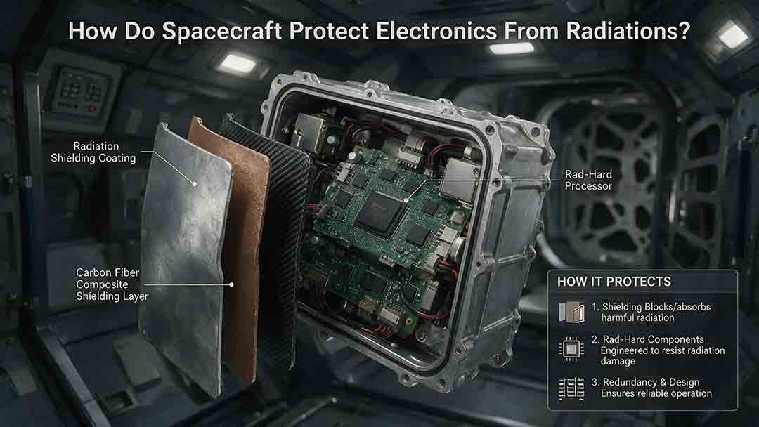
Spacecraft protect electronics from radiation through a layered engineering strategy rather than a single protective material. This article explains how total ionizing dose, displacement damage, single-event effects, and spacecraft charging can disrupt computers, memory, sensors, and power systems. It examines the roles of radiation-hardened components, physical shielding, error-correcting memory, current limiting, watchdog timers, redundancy, fault isolation, and safe-mode recovery. Readers will also learn how engineers model mission-specific radiation environments, evaluate the quality of component test evidence, estimate dose margin, and choose different protection strategies for Earth orbit, deep space, and high-radiation destinations such as Jupiter. Practical comparison tables, a decision framework, real mission examples, a troubleshooting guide, and a design-review checklist show why reliable spacecraft must be able to prevent, detect, contain, and recover from radiation-related faults.
How Does a Spacecraft Thermal Control System Work?
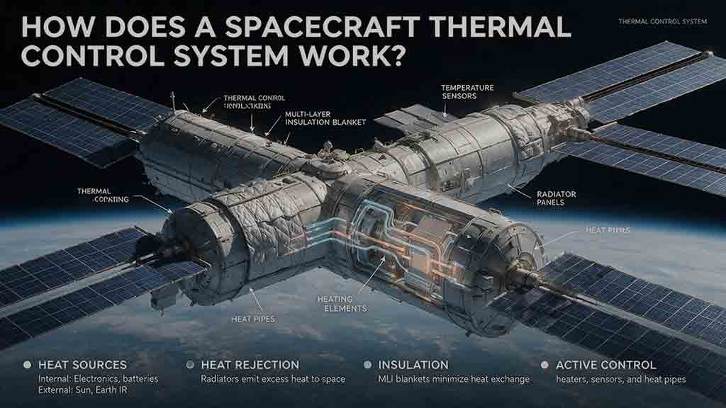
A spacecraft thermal control system keeps onboard equipment within safe operating and survival temperatures by controlling how heat is absorbed, generated, transported, stored, and released. This guide explains how passive technologies—including multilayer insulation, thermal coatings, heat pipes, straps, and radiators—work alongside active systems such as heaters, temperature sensors, cryocoolers, and pumped fluid loops. It introduces the original Protect–Move–Reject–Trim–Verify framework for understanding complete spacecraft heat paths and provides practical tools for evaluating thermal designs. Readers will also find a worked radiator-sizing example, a thermal-resistance calculation, mission-specific selection guidance, common design mistakes, troubleshooting methods, and real examples from the James Webb Space Telescope, International Space Station, and Europa Clipper. Based on publicly available NASA and ESA documentation, the article distinguishes simplified educational calculations from actual flight-design analysis while showing why spacecraft must be protected from both overheating and excessive cooling.
How Do Spacecraft Communicate With Earth?
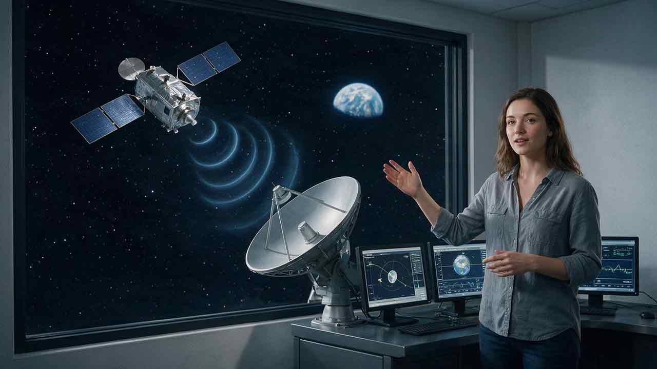
Spacecraft communicate with Earth by sending encoded information through radio waves or laser light. This guide explains the complete path from an onboard instrument and computer to a transmitter, antenna, ground station, and mission-control center. It covers uplinks, downlinks, telemetry, tracking, direct-to-Earth communication, relay satellites, spacecraft crosslinks, and onboard data storage. Readers will also learn why signals weaken over distance, how communication delays are calculated, and how antenna gain, transmitter power, data rate, coding, pointing accuracy, and ground-network availability affect link reliability. Worked examples show how long a signal may take to travel between Mars and Earth and how much data can be returned during a scheduled contact. Real mission examples—including NASA’s Deep Space Network, the Mars Relay Network, the James Webb Space Telescope, and the DSOC optical demonstration—show how these engineering principles are applied in practice.
Explore More Topics
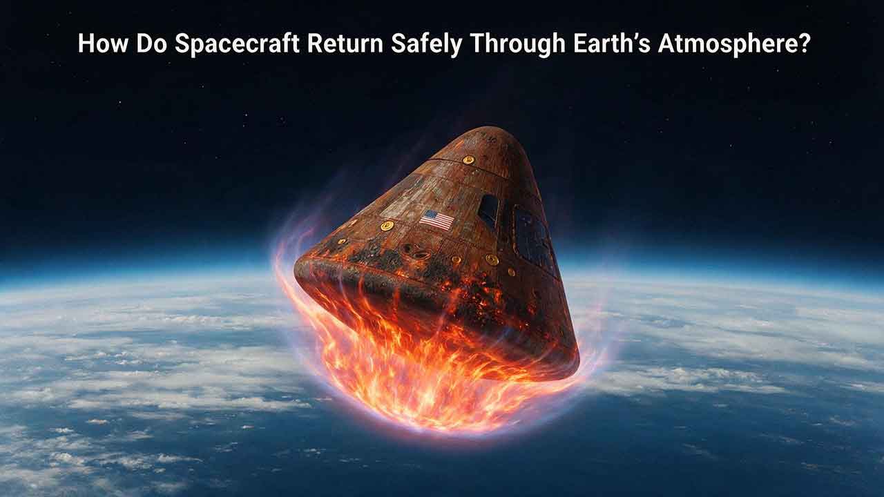
How Do Spacecraft Return Safely Through Earth’s Atmosphere?
Spacecraft return safely through Earth’s atmosphere by managing an enormous amount of energy through a carefully coordinated sequence of trajectory control, thermal protection, aerodynamic deceleration, landing, and recovery. This article explains how deorbit burns and entry corridors guide a spacecraft toward its landing region, why blunt heat shields reduce the danger of hypersonic heating, and how guidance systems control attitude, range, and structural loads. It includes an original comparison of low-Earth-orbit and lunar-return energy, a practical review of ablative and reusable heat-shield technologies, and the CosmoBasics Four-Layer Reentry Framework covering path, protection, control, descent, and recovery. Real-world lessons from Artemis I and the crewed Artemis II mission show why postflight inspection remains essential even after a successful splashdown. Readers will also learn how parachutes, wings, landing rockets, flotation systems, and recovery teams complete the return safely.
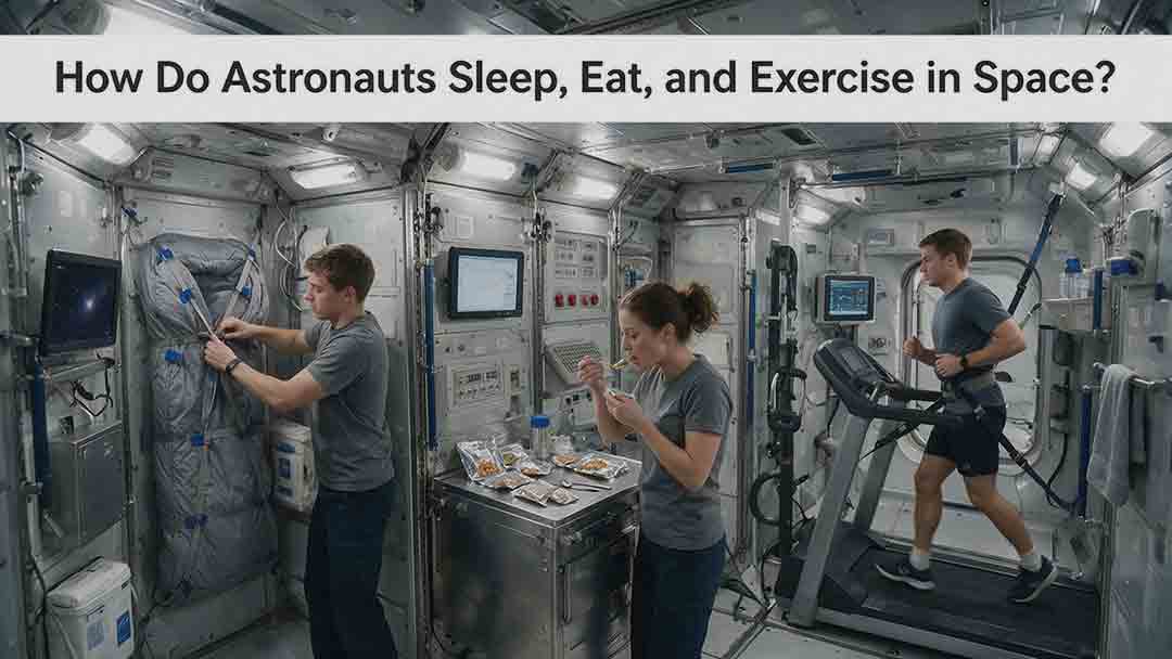
How Do Astronauts Sleep, Eat, and Exercise in Space?
Astronauts must redesign ordinary routines when they live in microgravity. This article explains how crew members sleep in secured bags inside ventilated quarters, prepare packaged meals without letting food or liquids drift through the cabin, and use specialized exercise equipment to protect their physical condition. It examines the roles of the Advanced Resistive Exercise Device, the T2 treadmill, and the CEVIS cycle ergometer, while clarifying the difference between active workout time and the full scheduled exercise period. Readers will also learn why tortillas are practical in space, how airflow affects sleep, why ordinary weights do not work normally in orbit, and how nutrition, rest, and exercise support one another. NASA and ESA sources provide the factual foundation, while original comparison tables and practical evaluation frameworks show how spacecraft systems replace functions normally supplied by gravity. The article also distinguishes current International Space Station practices from possible future Moon and Mars mission requirements.
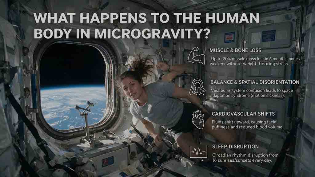
What Happens to the Human Body in Microgravity?
Microgravity changes the human body because fluids are no longer pulled toward the legs, muscles and bones receive less mechanical loading, and the brain loses gravity as a dependable orientation signal. This article explains how weightlessness affects balance, circulation, muscle strength, bone density, vision, blood, immunity, digestion, sleep, and spinal length. It also examines why astronauts may struggle to stand or walk after landing and how exercise, nutrition, monitoring, and rehabilitation help reduce these risks. Two original tools—the Load–Flow–Orientation Framework and the Gravity-Transition Readiness Matrix—connect physiological changes with real mission demands. Drawing on NASA standards, NASA technical reports, ESA materials, and peer-reviewed human spaceflight research, the guide clearly separates established observations from experimental countermeasures and unresolved questions. It also explains what these effects could mean for future missions to the Moon and Mars without treating population averages as predictions for individual astronauts.